
A beach wheel fits only when its complete mounting system matches the equipment. Diameter alone leaves bore, hub width, axle engagement and retention unresolved. This beach wheel size compatibility checklist helps purchasing and repair teams create a measurable replacement request before ordering parts.
Begin with the original equipment specification and a serviceable reference assembly. Compare candidate beach balloon wheels against that record. Treat a different size as a proposed equipment change requiring manufacturer review. Successful assembly in a workshop does not approve a wheelchair conversion.
Images are AI-generated illustrations based on product references. They do not document an actual inspection, factory visit, or project.
1. Which original equipment details should buyers capture?
Record equipment model, asset identifier, wheel position and current wheel part number. Photograph both sides of the installed assembly before removal. Include hardware order and any labels that distinguish left, right, front or rear components.
The beach wheelchair range contains different product configurations. A replacement enquiry should name the precise product and revision, rather than refer vaguely to an Ary wheel. Where identification has worn away, retain photographs and purchase records for supplier identification.
Use a serviceable reference where possible. A damaged axle or worn bore can produce measurements that describe wear rather than original design. Separate observed values from drawing requirements so a buyer does not order a new part around an existing defect.
- Identify wheel position and quantity required.
- Record equipment and wheel revisions separately.
- Photograph spacers, washers and retainers in order.
Start from an identified original assembly. Ask the equipment supplier to confirm its replacement specification before comparing alternative sizes.
Baseline identification record
| Field | What to enter | Why it affects replacement |
|---|---|---|
| Equipment | Model, revision and asset ID | Defines intended assembly |
| Position | Front, rear, left or right | Prevents positional mix-ups |
| Wheel | Part number and revision | Distinguishes similar-looking parts |
| Hardware | Photograph plus component order | Preserves mounting arrangement |
2. How should outside diameter and tire width be measured?
Measure a pneumatic wheel at its prescribed inspection pressure and condition. Record that condition with every dimension. For an unloaded diameter check, use a suitable measuring tool across opposite outer surfaces. Repeat at another orientation to identify inconsistent readings.
Measure maximum tire width separately from hub width. Avoid squeezing a flexible tire with caliper jaws; contact force can change the reading. Use parallel reference surfaces or another agreed method suitable for a soft shape. Follow the manufacturer’s dimensional procedure when available.
A wheel manufacturer’s comparison chart lists wheel dimensions and width at the bushing or bearing separately. That distinction supports separate measurements; its dimensions do not specify Ary components.
- Record units without mixing inches and millimetres.
- Note pressure and unloaded or loaded condition.
- Compare observed readings with specified tolerances.
Tire width and mounting width describe different spaces. Put both on the replacement drawing instead of sending one ambiguous “wheel width” value.
Outer-envelope measurements
| Measurement | Reference points | Record alongside value |
|---|---|---|
| Outside diameter | Opposite tire surfaces | Pressure and inspection condition |
| Tire width | Widest external tire faces | Method and contact force control |
| Loaded shape | Approved loaded setup | Load placement and procedure |
3. How do axle diameter and hub bore differ?
Axle diameter measures the shaft. Hub bore measures the receiving opening or fitted bearing/bushing interface. Measure the actual running surface, excluding threads, grooves and damaged ends. Use an instrument suitable for the required accuracy and compare several accessible positions.
For a bore, record the installed insert’s identity and internal dimension where measurement is permitted. An empty molded hub opening may differ from its working bore after a bushing is fitted. Do not remove a pressed component merely to collect a dimension unless approved service instructions permit that work.
Apply these checks to the exact all-terrain wheelchair assembly under review. This article supplies no universal clearance, interference fit or machining tolerance.
- Clean measurement surfaces using the approved method.
- Record instrument identity and resolution.
- Separate shaft wear from nominal shaft size.
A near match needs an engineering decision. Submit shaft and bore results together; do not enlarge a bore or grind an axle to force installation.
Shaft and bore worksheet
| Feature | Measurement location | Escalation trigger |
|---|---|---|
| Axle diameter | Clean running surface | Uneven or damaged surface |
| Working bore | Fitted running interface | Insert identity uncertain |
| Drawing fit | Specified dimensions and tolerances | Measurements outside approved limits |
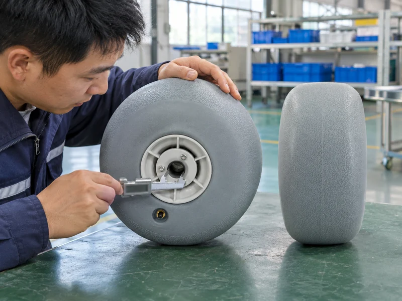
4. Which hub-width and axle-length measurements control fit?
Measure hub running width between locating faces that position the wheel on its axle. Include fitted sleeves or inserts when their faces define that span. Tire width can be larger or smaller, so keep both dimensions labelled.
Next identify usable axle length. Show the shoulder, spacer positions and retention feature on a sketch. A projecting shaft end is not automatically usable mounting length; a pin hole, groove or thread engagement requirement may consume part of it.
For an illustrative geometry check, compare the occupied stack of hub, approved spacers and washers with available mounting space. This check identifies possible conflicts. It does not establish acceptable end play or authorise substitutions on a lightweight beach chair.
- Mark contact faces on a photograph.
- List every component in the axial stack.
- Record required engagement from approved instructions.
Measure between working faces, then check the complete stack. Send the sketch with your enquiry so supplier and technician use identical reference points.
Axial fit record
| Dimension | Include | Do not substitute |
|---|---|---|
| Hub running width | Locating insert faces | Maximum tire width |
| Available mounting space | Shoulder-to-retention geometry | Total visible axle length |
| Occupied stack | Hub, approved washers and spacers | Hub body alone |
5. How should bearings, bushings and spacers be identified?
Record the running interface by part number, markings and approved drawing. Photograph any bearing seals, bushings, sleeves and spacer positions without assuming their internal construction. A wheel that slides onto an axle may still contain the wrong interface.
Ask whether a candidate wheel arrives complete or requires reuse of specified components. Reusing worn or unapproved parts can make a supposedly new assembly difficult to assess. Keep removed components labelled until the technician has reconciled their identities.
For a beach walker, equipment function also determines the review scope. A wheel substitution must account for controls and nearby structure where present. A cargo-wheel fit check cannot stand in for that equipment review.
- Confirm supplied versus reused components.
- Match insert, spacer and washer part numbers.
- Check permitted lubrication and cleaning instructions.
A wheel assembly includes its running hardware. Request one complete parts list with the candidate quotation and flag every proposed reused item.
Running-interface checks
| Component | Identification evidence | Decision required |
|---|---|---|
| Bearing or bushing | Marking and drawing reference | Correct for approved axle |
| Sleeve or insert | Part identity and fitted position | Supplied or reused |
| Spacer or washer | Thickness and sequence | Matches approved stack |
6. What proves that the retention system still works?
Confirm the specified retaining method and hardware. Depending on design, that may involve a pin, clip, nut or another locking arrangement. Review the original instructions rather than adding a convenient fastener from a workshop drawer.
After fitting by an authorised technician, inspect engagement according to that procedure. Record whether the retention feature can be reached, seen and operated as intended. A wider hub may leave insufficient room for its original retainer even though the wheel rotates.
For a beach cargo cart, document wheel removal requirements too. Frequent transport disassembly may make component identification and storage part of routine service. Do not translate that convenience into approval for quick-release modifications.
- Verify correct retainer and installed orientation.
- Check required engagement using supplied criteria.
- Record any tool or access obstruction.
Free rotation cannot prove secure retention. Place the assembly on hold if engagement differs from its approved configuration.
Retention review
| Check | Evidence | Hold condition |
|---|---|---|
| Hardware identity | Part number and photograph | Substitute of unknown suitability |
| Engagement | Model-specific check result | Incomplete or uncertain engagement |
| Service access | Removal/refitting demonstration | Access blocked by new hub or tire |
7. What clearances should a replacement wheel preserve?
Check the entire wheel envelope through permitted movement. Include nearby frame members, forks, guards and controls where fitted. Inspect turning positions and any specified folding or storage configuration. A straight-ahead workshop photograph captures only one position.
Record the smallest observed gaps with their measurement conditions. Loaded clearance checks require an approved procedure and equipment; do not improvise passenger trials to investigate an unapproved change. Different diameter can also change equipment geometry, so written manufacturer review remains necessary.
Use the appropriate current manual to define permitted movement and setup. Leave clearance criteria tied to that equipment rather than adopting a generic millimetre value.
- Inspect straight and turning positions.
- Check valve access where pneumatic wheels are fitted.
- Note contact marks, rubbing and trapped flexible parts.
A static gap can disappear during movement. Complete the prescribed clearance review and photograph its least-clear position.
Clearance map
| Area | Position to record | Possible conflict |
|---|---|---|
| Frame or fork | Full permitted movement | Tire or hub rubbing |
| Controls where fitted | Relevant operating positions | Restricted operation |
| Valve | Normal service position | Pump connection inaccessible |
| Folded equipment | Approved storage arrangement | Parts pressing against tire |
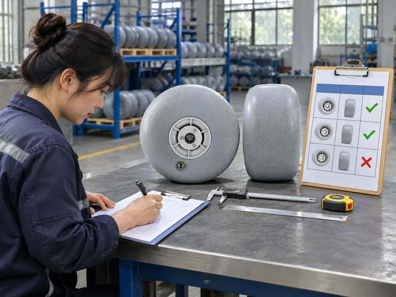
8. How should teams review load, pressure and route suitability?
Obtain ratings and pressure instructions for the complete candidate assembly. A wheel’s own rating does not replace the equipment manufacturer’s capacity or approval. Do not calculate a new chair capacity by multiplying a wheel figure by wheel count.
Identify the intended service route and loading conditions during manufacturer review. For different beach access applications, those conditions may include storage thresholds, firm paths and loose sand. Record each separately instead of labelling every surface “beach.”
After written configuration approval, perform agreed functional and route checks. Start with prescribed unloaded checks and progress only as authorised. Document wheel behaviour, control operation where relevant and any stop that prevented completion.
- Keep wheel and equipment limits separately identified.
- Use specified inflation methods for pneumatic tires.
- State route segments excluded from evaluation.
Component ratings cannot approve a complete equipment change. Obtain a decision covering the assembled product before trialling its proposed service role.
Suitability review
| Evidence | What it answers | What it does not answer |
|---|---|---|
| Wheel rating | Stated component conditions | New equipment capacity |
| Equipment approval | Permitted assembly and use | Conditions outside its scope |
| Route trial | Observed local operation | Universal terrain performance |
9. What should an incompatible measurement trigger?
Treat each mismatch as a specific engineering question. Identify the feature, original requirement, candidate result and requested disposition. Avoid a general note saying “does not fit” when a hub-width conflict can be described precisely.
A supplier may propose an approved alternative wheel or a reviewed assembly revision. Keep that proposal separate from technician improvisation. Drilling, grinding, changing spacer stacks or modifying retention can affect more than the visible mismatch.
Send the measurement sheet through Ary Beach technical support with photographs and equipment identification. Keep the old serviceable assembly available where policy permits. Do not cannibalise it before the replacement decision is clear.
- Describe one mismatch per line.
- Attach measurement conditions and drawing references.
- Record acceptance, replacement or rejection explicitly.
An incompatibility report should point to a measurable feature. Close each line with an authorised response before releasing parts for installation.
Mismatch register
| Finding | Useful report | Required outcome |
|---|---|---|
| Bore differs | Values plus insert identity | Approved compatible assembly |
| Retainer cannot engage | Stack sketch and photographs | Reviewed correction or rejection |
| Tire rubs | Position and contact location | Equipment-level review |
10. What belongs on the final replacement order?
Order a defined assembly with its approved equipment application. Include wheel part number, revision, position, quantity and supplied hardware. Attach the accepted drawing and list any separately ordered service components.
Keep commercial approval separate from installation release. A buyer can approve purchasing the correct part while a technician still needs to fit and inspect it. After installation, update the asset service record with fitting date, technician, part identity and completion evidence.
Retain the original and replacement records together. If a supplier later changes a hub, bearing or tire construction, those records support a fresh compatibility review. They also help prevent staff mixing old and new spare stock without checking revisions.
- Order by part number and revision.
- Reference original equipment manufacturer approval.
- Require inspection after fitting and before service.
Close your record around the installed assembly. Release equipment only after fitting, retention, clearance and authorised functional checks are complete.
Q1: Can matching nominal diameter prove compatibility?
Hub bore, running width, axle geometry, retention and equipment approval still require review.
Q2: Should a worn axle be used as the purchasing reference?
Record its condition, then compare against original dimensions. Ordering around wear can conceal the underlying repair requirement.
Q3: Can extra washers solve a loose wheel?
Use only the approved spacer arrangement. An improvised stack may alter retention engagement and running clearance.
Q4: Does a larger wheel automatically improve a wheelchair?
A larger diameter does not authorise conversion. Different geometry requires original equipment manufacturer review and approved checks.
Q5: What should accompany a replacement-wheel enquiry?
Send equipment identity, wheel position, original part number, dimensional sketch, hardware photographs and the exact mismatch or replacement need.