
A beach mat drawing should let a reviewer trace the travel surface from the first fixed landing across each joint to a usable destination. An outline labelled “proposed access mat” shows where the material goes. The engineer also needs elevations, the changing substrate, drainage paths, usable clear space and the interface between the product and the fixed works.
Start by agreeing the limits of the assignment. Identify the site owner, the authority responsible for access and environmental requirements, the supplier responsible for the offered system detail, and who reviews field departures from the design. Include service traffic, seasonal removal and any boundary beyond which the route is not intended to operate.
Tie the survey to points the installer can find
Use a stated coordinate and elevation reference, survey date and units. Give the route an origin and mark stations at each change of grade, direction, surface or restraint detail. Survey the approach far enough back to capture the movement into the route, and the destination far enough beyond the last section to show the turn and return.
At a landing, record the actual travel-surface elevation and the supporting surface on the proposed mat side. Allow for the thickness and geometry of the offered section and end detail. Measure clear width between real obstructions, including gates in their operating positions. A tape held across an open fence bay can overstate the space visitors have when the gate leaf and furniture are in place.
Mark drainage outlets, ponded areas, sand deposits, evidence of scour and nearby maintenance crossings on the same plan. Photograph each observation with station, direction and date. If only dry-weather conditions have been observed, identify where wet-weather evidence is still needed before a detail can be accepted.
Draw the interface at the scale of the discrepancy
Provide a longitudinal profile and cross-sections where the approach, surface or crossfall changes. Show the finished top surface and the supporting ground as distinct lines. In an enlarged transition detail, label which face of the fixed landing and which face of the installed end piece the inspector should measure.
For a hypothetical field check, assume a landing is at 2.410 m and the adjacent installed mat top is at 2.385 m, on the same datum. The difference is 0.025 m, or 25 mm. A person returning from the mat approaches the higher surface. Record the location, direction, measured difference and joint geometry. Compare them with the project’s applicable requirements and accepted detail. This calculation illustrates the observation and supplies no universal allowable step.
A grade averaged over the whole route could hide that interface. Check longitudinal and cross conditions over their actual measured segments. Where an applicable standard sets criteria, put the reference beside the measurement and show how the project reviewer applied it. The U.S. Access Board explains the federal scope of its outdoor developed-area provisions and separately discusses surface firmness, stability and slip resistance under the ADA Standards. Outdoor developed areas guide · Floor and ground surfaces guide
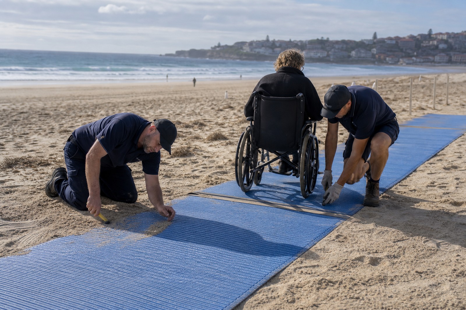
Coordinate the product detail, ground and water movement
Request the offered section drawing, mating ends, edge detail, permitted fixing method and conditions for which the supplier provides evidence. Ary describes modular interlocking sections and a route length configured by section quantity. Use dimensions and installed coverage tied to the specific offer when placing joints on the plan. Record how an approved replacement section will be removed and how adjoining sections will be checked after refitting. Beach access mat product information
Review runoff across and along the route. A low point that collects sand or an outlet discharging near an end piece can change support between inspections. Show how the maintenance crew reaches that location without blocking the only usable return. Where restraint requires ground penetration, establish the actual ground conditions, restrictions and approved design responsibility before issuing a fixing detail. An anchor shown in another project’s drawing cannot establish spacing or resistance here.
If vehicles or carts must cross, identify their proposed movements, loads, frequency and control arrangements. Keep the crossing outside the public service until its design and operating use have been reviewed. A pedestrian route description supplies no verified vehicle capacity.
Issue the drawings with an inspection method
| Drawing or schedule | What the reviewer can verify in the field |
|---|---|
| Numbered alignment, profile and sections | Station, finished levels, clear width, crossfall and usable turning area under the agreed setup. |
| Enlarged landing and end detail | Actual faces measured, surface support, connection fit and any local change in level. |
| Drainage and crossing plan | Location of outlets, observed water paths, access for maintenance and control of conflicting traffic. |
| Section and fixing schedule | Offered part references, mating joint locations, approved fixing detail and work to inspect before it is concealed. |
Require the contractor to mark variations against their exact stations. If sand levels or a drainage condition differ from those assumed, record the field condition before deciding on preparation, a revised connection or a changed alignment. Review the affected portions again after correction. Contractor handover and field changes
Give operations the as-built layout, retained survey references, critical inspection points and conditions requiring another technical review. A newly exposed fixing, persistent ponding at the same station or movement after a storm gives the duty team a specific location and action. It also lets the engineer compare the later condition with the geometry that was accepted.